20 KV VOLTAGE DISTRIBUTION AND GRID CONTROL SYSTEM TRAINER
20 KV VOLTAGE DISTRIBUTION AND GRID CONTROL SYSTEM TRAINER
Overview:
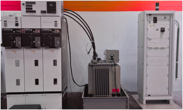
A comprehensive training system for understanding real-world medium-voltage power distribution, metering, switching, protection, and customer-side load management. Designed to simulate 20 kV grid operations, transformer-based step-down systems, and distribution to residential/commercial units with full electrical safety compliance
Key Educational Objectives:
- Study of 20 kV to LV distribution methodology.
- Understanding Current Transformer (CT) metering and wiring.
- Load balancing, measurement, and energy accounting via KWh meters.
- Polarity testing and wiring safety compliance.
- Analysis of switching, fault isolation, and protective relay integration.
- Hands-on experiments with live load modules like motors, heaters, and lighting circuits.
System Includes the Following Modules:
1. Current Transformer Metering Connection Board
General Specifications:
- 1× Digital KWH Meter (3-Phase)
- 1× Metering Test Block
- 1× Bridging Link
- 3× Current Transformers (CTs)
- 3× Protection Fuses
- 1× Main Circuit Breaker (Switch Type)
- 1× Lockable Isolation Compartment
- Made from heavy-duty steel
- Epoxy powder-coated finish
- Engraved and silk screen legends for component identification
2. Multi-Customer Metering Arrangement Board
General Specifications:
- 3× Non-Fused Breakers (NFBs)
- 1× Fuse Switch Disconnector
- 15× Main Circuit Breakers:
- MCB 1P, 32A – for high-load customers
- MCB 1P, 20A – for standard connections
- 1× Current Limiter
- Sealable Active Links:
- 1× 7-Hole
- 1× 5-Hole
- 12× Protection Fuses
- Energy Meters:
- 3× Single-Phase Digital KWH Meters
- 9× Single-Phase Analog/Digital KWH Meters
- Heavy-gauge steel compartment with printed legend, for metering and fuse management
3. Application & Load Module Pack
Includes industrial-grade plug-and-play load simulation units:
- Lighting Module
- Outlet Socket Module
- Single-Phase AC Motor Module
- Heater Module
Each module enables connection with the main board for real-time current flow, voltage drop, and power monitoring exercises.
4. Distribution Board Trainer with Polarity Test Panel
General Specifications:
- 2× Emergency Isolators (for safety disconnection)
- 3× Indicator Lamps
- 3× Protection Fuses
- 1× Three-Phase Contactor
- 1× Mechanical Interlock System
- 1× Smart Meter (3-Phase energy and load data monitoring)
- Protection Devices:
- RCD (Residual Current Device)
- MCBs (1P and 3P configurations)
- Wiring Infrastructure:
- Main Box + MCB Box
- Earth Electrode for practical earthing study
- GPO (General Power Outlet) with single power point
- Load Fixtures:
- Lamps + Lamp Holders
- Switch (1-Way)
- Cover Boxes, Selector Switches
- Insulated Busbars
- Protection & Automation:
- Relay with Socket Base for logic protection/controls
All components are housed in heavy-gauge, epoxy powder-coated steel enclosures with front-access legends and safety features for student operation.
Power & Safety Specifications:
- System designed for 20 kV incoming simulation (with scaled-down safe voltage interface for labs)
- All high-voltage circuits are internally simulated via controlled power electronics
- All modules include short-circuit and overload protection
- Compliant with IEC/IS safety standards
- Fully enclosed compartments with padlock provision
Software & Control Integration:
- Optional SCADA or Remote-Control Interface available
- Data logging for current, voltage, power factor, and energy
- Real-time graphical monitoring on PC (optional)
- Report generation support for classroom evaluations
Additional Accessories:
- Frequency Meter
- Power Factor Meter
- Distribution Transformer (for step-down simulation)
- Control Desk Table + Operator Station
Documentation and Certification:
Supplied with:
- Trainer and Student Manuals (Hard + Soft Copy)
- Circuit Diagrams and Wiring Layouts
- Component Technical Sheets
- Worked Experiments and Exercises
- OEM Certificate of Conformity
- Global Trainee Certification (where applicable)