Analog Digital Trainer Kit (VPEDU-DL-ADBT)

DigitalTrainer_VPEDU_DL_ADBT_Front
DigitalTrainer_VPEDU_DL_ADBT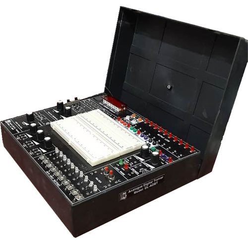
DigitalTrainer_VPEDU_DL_ADBT_Side
DigitalTrainer_VPEDU_DL_ADBT

ADBT-StudyCards_Optional
Optional Study Cards.This Digital Trainer Kit with Bread Board has been designed with the idea of providing basic facilities essential for conducting simple experiments in the laboratory. Using these facilities one can get familiarized with the various digital ICs.
Using this trainer, one can get familiarized with the various digital ICs. The system is suitable for conducting experiments on TTL ICs. The system has an onboard facility of four crystal generated clock output of 1MHz, 100Hz, 10Hz & 1Hz. It has a facility of Single Pulse Generation by push button switch. Four Seven Segment Display with BCD inputs having breadboard area facility of 1200 TIE points.
Salient Features:
- Ready to use circuit boards (optional)
- On Board DC power supply.
- On Board 100 KHz Function Generator
- 2 Pulser switches, 10 data input switches.
- Bicolor LED display & Logic probes.
- BCD to seven segment display.
- Fixed TTL Clock of 0.1Hz and 1Hz.
- More than 20 designed experiments for breadboard.
- Fictional blocks indicated on board mimic.
- Optional ready to use circuit boards.
Technical Specifications:
- Breadboard : 172.5 mm × 128.5 mm
- Tie Points : 1685
- DC Power Supply : + 5V – 1A, -5V 500mA, +15V, -15V (fixed)
- 0V to 15V 500 mA (variable),
- 0V to -15V, 500mA (variable)
- Pulse/Function Generator
- Frequency Range : 10 Hz to 100 KHz in 5 steps Variable in between
- Duty cycle : 50%, TTL output
- Pulser switches : 2 Nos. (Push to On)
- Data Switches : 10 Nos. (Toggle Switches for both TTL)
- LED Display : 10 Nos. (TTL Mode)
- Seven Segment Display : 4 Nos.
- Logic probe : Logic Level Indicator for TTL
- Potentiometer : 3 Nos.
- Power : 220V ± 10%, 50/60 Hz
- Power Consumption : 3VA (approx)
- Accessories Included : Mains cord, Operating and experimental Manual (with more than 20 designed experiments), patch cords.
Experimental Modules (Optional):
- HALF/FULL ADDER AND SUBTRACTOR
- Half Adder
- Full Adder
- Half Subtractor
- Full Subtractor
- MULTIPLEXER & DEMULTIPLEXER
- Multiplexer
- Demultiplexer
- ENCODER & DECODER
- Encoder
- Decoder
- STUDY OF FLIP-FLOPS
- RS Flip-Flop using NAND Gates
- D Flip-Flop
- JK Flip-Flop
- COUNTERS
- Asynchronous Counter
- 4 Bit Binary Asynchronous Counter
- SHIFT REGISTER (SISO/SIPO)
- Serial IN Serial OUT
- Serial IN Parallel OUT
- Bidirectional Shift Register (74194)
- MODULE N COUNTER & DECADE COUNTER
- 7493 – 8 Bit Binary Counter
74190 – Up-Down Counter with Preset
- 7493 – 8 Bit Binary Counter
- DIGITAL LOGIC GATES
- NAND Gates (7400)
- NOR Gate (7402)
- NOT Gate (7404)
- AND Gate (7408)
- OR Gate (7432)
- EX-OR Gate (7486)
- ANALOG ADC/DAC
- Analog to Digital Converter
- Digital to Analog Converter
- MEMORY EXPERIMENT PANEL
Note: Images given are for representation only and the final equipment can vary according to the specifications.