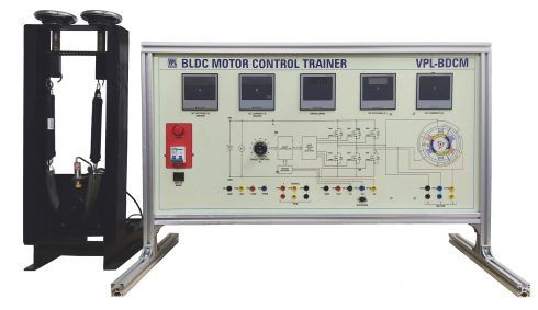
BLDC Motor Control Trainer (VPL-BDCM)
The BLDC motor uses the quadrature encoder for rotor position sensing. The quadrature encoder output consists of three signals. Two phases, A and B, represent the rotor position, and an index pulse defines the zero position.
Brushless DC motors typically use trapezoidal control, but field-oriented control is used as well. PMSM motors typically use field-oriented control only. Trapezoidal BLDC motor control is a simpler technique than field-oriented control; it energizes only two phases at a time. Only one PID controller is required for torque control, and as opposed to field-oriented control, there is no need for coordinate transformations using Park and Clarke transforms.
BLDC motors are commonly used in these E-bikes. The best part is that these BLDC motors have hall sensors built-in. The Hall effect sensors, which are used to detect the rotors position, can also be used to determine speed by measuring the time it takes for the sensors to switch.
The BLDC Motor is Popularly known as a scooter motor or general application motor. It is extremely durable and reliable. It's Commonly found in 48/60V scooters and It's also been a proven motor in robotics.
SPECIFICATIONS:
- Microcontroller based Motor Controller
- Rated Voltage: 48V
- Maximum Power: 1500W
- Maximum Speed: 3200 RPM
- Winding Resistance: 9.2 Ohms
- Winding Inductance: 24mH
- Front panel consists of Digital Meter, RPM Meter and circuit is printed on.
- 4 Pole Rotor and 3 Phase motor
- Fixed on a mechanical frame
- Spring balance loading with dial indication
- Hall sensor for position sensing
- To study the working of BLDC Motor
- To study the speed control of BLDC Motor
- To study speed torque characteristics
- Manual with detailed operation and experiments.
Note:
Specifications can be changed and added without notice in our constant efforts for improvement.
Images given are for representation only and the final equipment can vary according to the specifications.

