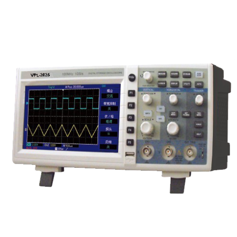
Digital Storage Oscilloscopes (VPL-2025)
CHARACTERISITCS
- Bandwidth : 25MHz
- Real-time Sampling Rate : 500MS/s
Sampling
- Equivalent sampling : 25 GS/s
- Sampling : Sampling, peak detect, average
- Average value : When all channels have made N samplings simultaneously, N is selectable from 2, 4, 8, 16, 32, 64, 128 to 256
Input
- Input coupling : DC, AC, GND
- Probe attenuation factor : 1X, 10X, 100X, 1000X
- Input impedance : 1MW±2% in parallel with 20±3pF
- Maximum input voltage : 400V (DC + AC Peak, 1MW input impedance)
- Time delay between : 150ps
- channels (Typical)
Horizontal
Waveform interpolation : Sin (x) / x
Record Length : 1024K
Scanning range (s/div) : 2ns/div-50s/div
Accuracy of sampling rate : ±50ppm
and delay time (any time interval =1ms)
Time interval (DT) : Single : ± (1 sampling time Measurement accuracy interval + 50ppm x reading (full bandwidth) + 0.6ns);
16 average values : ± (1 sampling time interval + 100ppm x reading + 0.4ns)
Vertical
- A/D converter : 8-bit resolution
- Deflection factor range : 1 mV/div ~ 20V/div (at input BNC)
(VOLTS/DIV)
Power Source
- Source Voltage : 100 – 240VACRMS, 45-440Hz, CAT II
- Power Consumption : Less than 30VA
- Fuse : F1.6AL 250V
Trigger
- Trigger sensitivity : Internal trigger : £ 1 div; external
- Trigger level range : ± 8 div from the centre of the screen
- Trigger level accuracy : ± (0.3 div x V/div) (within ± 4 div
- (Typical) applied on signals from the centre of the screen) of ³20ns rise or fall time
- Pretrigger capability : Normal mode/scanning mode, pretrigger/delayed
- Trigger. Pretrigger depth is adjustable
- Holdoff range : 100ns – 1.5s
- trigger : £ 0.2V
- Set level to 50% (Typical) : Input signal frequency =50Hz
Edge Trigger
- Edge type : Rise, fall, rise and fall
Pulse Trigger
- Trigger mode : (Greater than, less than or equal to) positive pulse; (Greater than,less than or equal to) negative pulse
- Pulse width range : 20ns – 10s
Alternate Trigger
- A Trigger : Edge, pulse
- B Trigger : Edge, pulse
Measurement
- Cursor:
*Manual mode : Voltage difference (DV) between cursors; time difference (DT) between cursors; time difference (DT) countdown (Hz) (1/DT)
*Automatic measurement mode : Cursor display is enabled during measurement
*Tracking model(25MHz) : Voltage or time value of waveforms dots
- Automatic measurement : Peak-to-peak, amplitude, maximum, minimum, top, bottom, mean, average, root mean square, overshoot, preshoot, frequency, cycle, rising time, falling time, positive pulse, positive pulse negative pulse, positive duty ratio, negative duty ratio, delay.
- Customized parameter measurement : 3 types
- Math functions : +, -, x, ÷
- Saving waveforms:
*Internal : 20 groups of waveforms and 20 setups
FEATURES
- 500MSa/s / 1GSa/s Sampling Rate
- 2 Channels
- 7 in LCD Color Display
APPLICATIONS
- Industrial Power Design, Troubleshooting, Installation, and Maintenance.
- Electronics Design, Troubleshooting, Installation, and Maintenance
- Circuit Design & Debug
- Educational Lab & Training Institutions
- Repair & Service
- Production Test & Quality Inspection
Position range : ± 10 div
Analog bandwidth : 25MHz
Single bandwidth : 25MHz
Selectable analog : 20MHz
bandwidth limit (Typical)
Low frequency response : £ 10 Hz at BNC
(AC coupling, -3dB)
Rise time : £3.5ns, £7ns at 100MHz and 50MHz bandwidths respectively
DC gain accuracy:
*When vertical sensitivity is 1mV/div~2mV/div: ±5% (sampleor average acquisition mode);
*When vertical sensitivity is 5mV/div: ±4% (sample or average acquisition mode);
*If vertical sensitivity is 10mV/div~50V/div : ±3% (sample or average acquisition mode)
DC measurement accuracy (average acquisition mode):
*When vertical position is zero and N =16 :
± (5% x reading + 0.1 div + 1mV) and 1mV/div~2mV/div is selected;
± (4% x reading + 0.1 div + 1mV) and 5mV/div is selected;
± (3% x reading + 0.1 div + 1mV) and 10mV/div~50V/div is selected;
*When vertical position is not zero and N =16:
± [3% x (reading + vertical shift reading) + (1% x vertical shift reading)] + 0.2div). Set from 5mV/div to 200mV/div plus 2mV;
*Setup value > 200mV/div to 50V/div plus 50mV.
Voltage difference (DV) : Under identical setup and environmental conditions, the voltage difference measurement accuracy (DV) between any two points of the waveform after the average of =16
(average acquisiton mode) waveforms acquired waveforms is taken : ± (3% x reading + 0.05 div)
Note: Specifications can be changed, added or subtracted without notice in our constant efforts for improvement.

