PID Controller Trainer (VPL-CL-PID)
DESCRIPTION
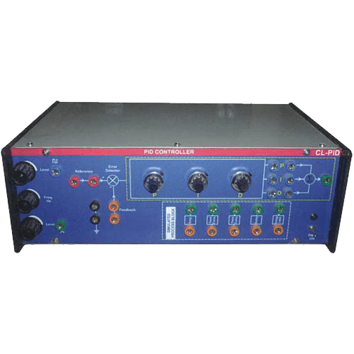
This set up is designed to study performance of analog PID Controller with simulated process. The board has built in signal source, building blocks for simulated process and PID Controller with built in regulated dc supply to operate the system.
The PID Controller has three adjustable parameters, as P, I, D each has 10 turn potentiometers with dial knobs which are subdivided for .02 resolution. Three sockets are provided to add or out any of desired control P, I or D. at input of PID controller an adder is provided which sums the reference and feedback signals. The input and output of PID control has no phase shift.
- General Details
The PID Controller has three adjustable parameters, as P, I, D each has 10 turn potentiometers with dial knobs which are subdivided for .02 resolution. Three sockets are provided to add or out any of desired control P, I or D. at input of PID controller an adder is provided which sums the reference and feedback signals. The input and output of PID control has no phase shift.
Note: Specifications of any product can be changed or added without notice in our constant efforts for improvement.
- TECHNICAL SPECIFICATIONS
- Study of a simulated PID controller.
- PID Controller (configurable as P, PI, PD and PID).
- Proportional band : 1% to 50%.
- Gain : 0-20.
- Integral time : 10 mS – 100 mS.
- Derivative time : 2-20 mS.
- Signal sources : Square wave : 0-2Vpp at 10-40 Hz variable (typical).
- Built in IC regulated power supplies.
- 220V ±10%, 50Hz mains operated.
- User’s Manual with patch cords.
Note: Specifications of any product can be changed or added without notice in our constant efforts for improvement.
- LIST OF EXPERIMENTS
- Study of open loop response of various process.
- Study of close loop response.
- P, PI & PID design and performance evaluation in each case.

