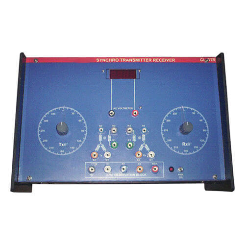
Synchro Transmitter Receiver Trainer (VPL-CL-STR)
DESCRIPTION
A Synchro Transmitter Receiver (STR) Trainer is an electromagnetic transducer commonly used to convert an angular position of a shaft into an electric signal. It is usually called a synchro transmitter. Its construction is similar to that of a three phase alternator. It consists of Sator, Rotor, Synchro Transmitter and Synchro Receiver.
- General Details
A Synchro Transmitter Receiver (STR) Trainer is an electromagnetic transducer commonly used to convert an angular position of a shaft into an electric signal. Its construction is similar to that of a three phase alternator. The stator (stationary member) is of laminated silicon steel and is slotted to accommodate a balanced three phase winding which is usually of concentric coil type (three identical coils are placed in the stator with their axis 120 degrees apart) and is Y connected. The rotor is a dumb bell construction and wound with a concentric coil. The system set up is made up of synchro transmitter and synchro receiver on a single rigid base provided with suitable switches and anodised angular plates. The system also contains a step down transformer for providing excitation to the rotors. Suitable test points for rotor (R1 and R2) and stator (S1, S2 and S3) for both Tx and Rx are provided.
Note: Specifications of any product can be changed or added without notice in our constant efforts for improvement.
- Technical Specifications
- Study of input/output angular displacement.
- Pointers on transmitter and receiver.
- Rotor R1, R2 & R3 Stator S1, S2 & S3 on panel.
- Built in isolated power supply.
- 220V ±10%, 50Hz mains operated.
- Attenuated output for signal observation on CRO.
- User’s Manual with patch cords.
Note: Specifications of any product can be changed or added without notice in our constant efforts for improvement.
- List of Experiments
- Study of Starter voltage of the rotor angle, the space variations of the three voltages V12, V23 & V31 due to rotation of resultant magnetization in the starter for the error detection process.
- Plotting the error voltage as a function of the rotor angle with the receiver rotor for observing the 180° of phase reversal around the zero error.
- Error study of the transmitter and receiver pair as a simple open loop position control at a very low torque.
- Related Products
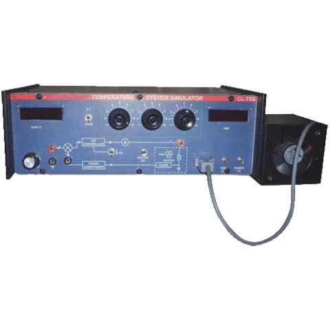
Temperature System Simulator (VPL-CL-TSS)
DESCRIPTION
This set up is designed to study performance of analog PID controller with model process as temperature control system. The set up has built in signal source as reference, digital voltmeter as temperature indicator, PID controller with separate controls and a model process with built in regulated DC supply to operate the system.
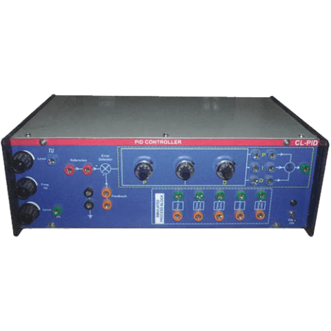
PID Controller Trainer (VPL-CL-PID)
DESCRIPTION
This set up is designed to study performance of analog PID Controller with simulated process. The board has built in signal source, building blocks for simulated process and PID Controller with built in regulated dc supply to operate the system.
The PID Controller has three adjustable parameters, as P, I, D each has 10 turn potentiometers with dial knobs which are subdivided for .02 resolution. Three sockets are provided to add or out any of desired control P, I or D. at input of PID controller an adder is provided which sums the reference and feedback signals. The input and output of PID control has no phase shift.