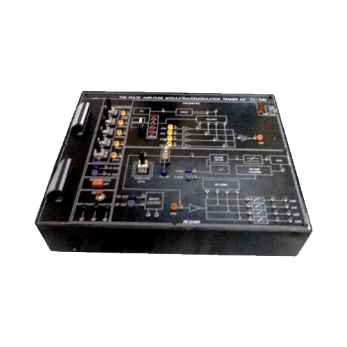
TDM Pulse Amplitude Demodulation Transmitter Trainer (VPL-CT-TDM)
SALIENT FEATURES
- Crystal controlled Clock.
- On – Board Sine Generator (Synchronized).
- On – Board Pulse Generator.
- 4 Analog input Channels samples and Time Division Multiplexed.
- Pulse Duty cycle selected.
- 4 Channel De multiplexer.
- Generation of clock at Receiver by PLL system.
- 4th order Butterworth L.P. Filters.
TECHNICAL SPECIFICATIONS
- Crystal Frequency : 6.4/8 MHz.
- Analog Input channel : 4.
- Multiplexing : Time Division Multiplexing.
- Modulation : Pulse Amplitude Modulation.
- On – Board Analog Signal :250 Hz, 500 Hz, 1 KHz, 2KHz 500 Hz, 1 KHz, 2KHz, 4KHz (optional).
- Sampling Rate : 16 KHz / Channel.
- Sampling Pulse : With Duty Cycle variable from 0 – 90% in decade steps.
- Clock Resistance at Receiver : Using PLL.
- Low Pass Filter cut – off Freq. : 3.4 KHz.
- Fault Switches : 4 nos. through 4 way DIP switch for troubleshooting at different blocks.
- Test Points : More than 50.
- Interconnections : 2/4 mm socket.
- Cabinet : Enclosed in ABS plastic cabinet with detachable cover.
- Power : 220V AC ±10%, 50/60Hz mains operated.
- Accessories : Set of Patch Cords, User’s manual.
LIST OF EXPERIMENTS
- Pulse Amplitude Modulation technique.
- Time Division Multiplexing and De multiplexing.
- PLL as Frequency Multiplexer to Generate clock from Sync signal.
- 3 modes of operation to generate original signal.
- 3 connections between transmitter & receiver (Clock, Sync & Information).
- 2 connections (Information, Sync) Clock gen. at receiver.
- 2 connection (information only), clock and Sync derived at receiver.
- Effect of varying duty of sampling pulse on signal reconstruction..
OPTIONAL ACCESSORIES
♦ Multimedia interactive computer based training manual

