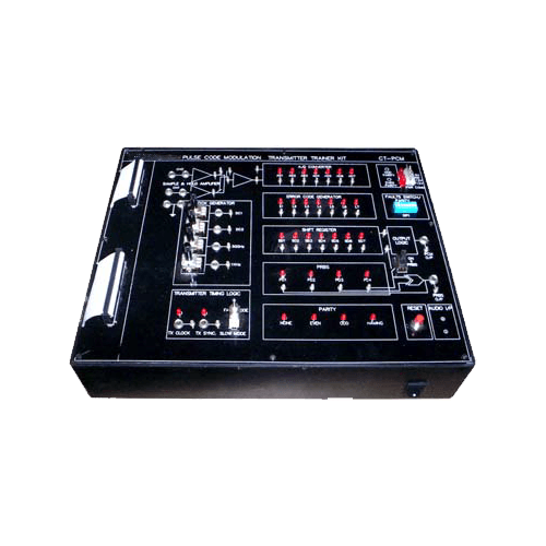
TDM Pulse Code Modulation Transmitter Trainer (VPL-CT-PCM)
TECHNICAL SPECIFICATIONS
- Crystal Frequency : 12/16 MHz
- On – Board Generators :
- – Adjustable Amplitude sine Generator of 500Hz & 1KHz (synchronised) 1 & 2 KHz synchronized frequency (optional)
- – Variable Amplitude DC Level (2 nos.)
- Input Channels : Two
- Multiplexing : Time Division Multiplexing
- Modulation : Pulse Code Modulation
- Sync Signals : Pseudo Random Sync. Code Modulation
- Error Check Code Off – Odd – Even – Hamming
- Operating Modes : Fast 240 KHz / Channel (approx) Slow 1 KHz Channel (approx)
- PC – PC Communication : 2 Channel via RS 232
- Port : 9 Pin D – type Connector 2 nos.
- Baud rate : Selectable from 300 to 2400
- Fault Switches : 8 nos. through 8 way DIP switch for troubleshooting at different blocks
- Test Points : More than 45
- Interconnections : 2/4 mm socket
- Cabinet : Enclosed in ABS plastic cabinet with detachable cover
- Power : 220V AC ±10%, 50/60Hz mains operated
- Accessories : Set of Patch Cords, User’s manual
LIST OF EXPERIMENTS
- Pulse Code Modulation
- A/D Converter, Parallel to serial Data conversion
- Time Division Multiplexing of PCM Data
- Synchronization by Pseudo random code Error check codes with switched faults
- Connecting modes between transmitters & receiver
- i) Sync, clock, data line connected
- ii) Clock, data connected – Data Only
- PC – PC communication in 3 modes
OPTIONAL ACCESSORIES
♦ Multimedia interactive computer based training manual

