Universal Embedded/VLSI Trainer (VPL-ET)
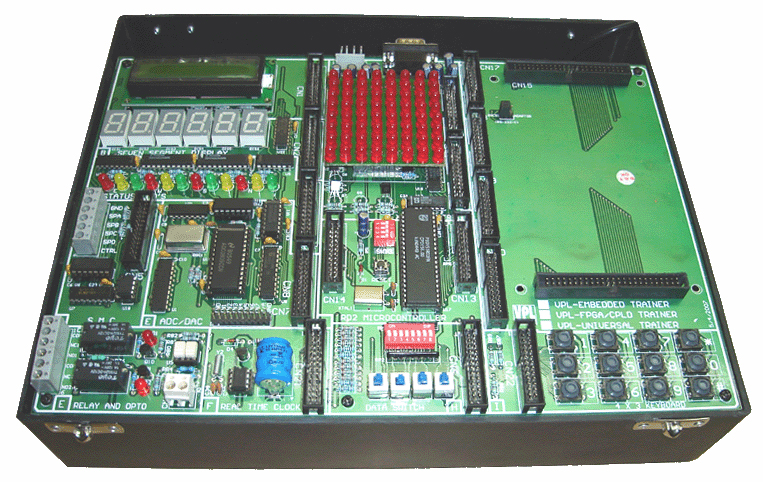
Universal Embedded/VLSI Trainer (VPL-ET)
FEATURES
- It has optional daughter boards like 8051, PIC, AVR, ARM, Microchip PIC16F877/16F876/16F84, Motorola 68HC11, Spartan II, Spartan III, Spartan VI, CPLD etc.
- It has level microcontroller 8051 family processor to enable it to upload and download program to various other 8,16 ,32 bit microcontrollers
- It has a Serial/Parallel/USB (JTAG) link which enable user to communicate with PC.
- User can develop the circuit using different Software and any development tool for design available in the world.
- It has I/O counter interface to enable it to connect various demo modules. This helps in man to machine interface.
- Two 50 pin headers provided for interfacing daughter boards.
- Has a general purpose areas on board to enable it to incorporate additional circuit.
Peripheral Features for 8051
- On-chip Flash Program Memory with In-System Programming (ISP) and In-Application Programming (IAP) capability
- Can be programmed by the end-user application (IAP)
- 6-clock/12-clock mode Flash bit erasable and programmable via ISP
- 6-clock/12-clock mode programmable “on-the-fly” by SFR bit
- Peripherals (PCA, timers, UART) may use either 6-clock or
- 12-clock mode while the CPU is in 6-clock mode
- Speed up to 20 MHz with 6-clock cycles per machine cycle (40 MHz equivalent performance); up to 33 MHz with 12 clocks per machine cycle
- Fully static operation
- Four interrupt priority levels
- Seven interrupt sources
- Four 8-bit I/O ports
- Full-duplex enhanced UART
- Framing error detection
- Automatic address recognition
- Power control modes
- Clock can be stopped and resumed
- Idle mode
- Power down mode
- Programmable clock-out pin
- Second DPTR register
- Asynchronous port reset
- Low EMI (inhibit ALE)
- Programmable Counter Array (PCA)
- PWM
- Capture/Compare
ON-BOARD INTERFACES
- 16×2 LCD module
- Six Seven Segment Displays
- Stepper Motor Controller Interface
- 8×8 LED Matrix Display
- EWSN Status LED’s 12 Nos.
- ADC/DAC Interface
- RS-232 interface
- USB interface
- Four Data Switches
- Switch Array
- AT24C16 Serial EEPROM
- 4×4 Keyboard
- Power Indicator LED
- Bluetooth Interface
- GSM Interface
- Zigbee Interface
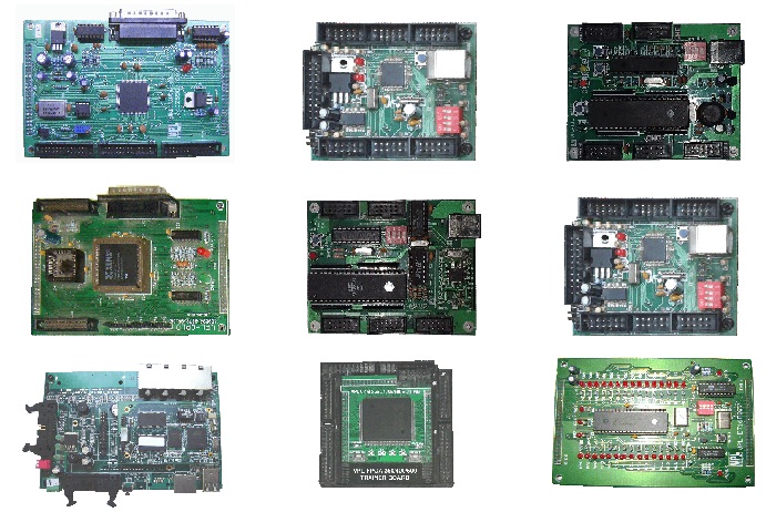
DAUGHTER BOARDS:
1. Board for Atmel 8051
With this board you can develop and prototype with any of 8051 (AT89S51, AT89S52, P89V51RD2, AT89Cxx) 40 pin microcontrollers. The board have and status LED. The 1.5 Amp bridge rectifier allow this board to be powered with both AC and DC power supply adapters. Board having USB port for flashing P89V51RD2 (NXP) microcontroller. There is 5V, 12V, GND power bus which allow to power external peripherals module.
FEATURES:
-
- DIP40 microcontroller socket.
- Quartz crystal 11.05892 Mhz.
- USB Interface for communication with PC.
- Reset button.
- ON – OFF switch.
- Power plug-in jack.
- Extension slot on every uC pin.
- GND bus.
- Vcc bus.(5V and 12V).
- On board power indication.
- Two 50 pin headers provided for interfacing with main board.
2. Board for Microchip PIC16F84
With this board you can develop and prototype with Microchip PIC16F84 microcontrollers. The board have and status LED. The 1.5 Amp bridge rectifier allow this board to be powered with both AC and DC power supply adapters. Board having USB port for downloading sample programs. There is 5V, 12V, GND power bus which allow to power external peripherals module.
FEATURES:
-
- DIP microcontroller socket.
- USB Interface for communication with PC.
- Reset button.
- ON – OFF switch.
- Power plug-in jack.
- Extension slot on every uC pin.
- GND bus.
- Vcc bus.(5V and 12V).
- On board power indication.
- Two 50 pin headers provided for interfacing with main board.
High Performance RISC CPU:
-
- Only 35 single word instructions to learn
- All instructions single cycle except for program branches which are two-cycle
- Operating speed: DC – 20 MHz clock input
- DC – 200 ns instruction cycle
- 1024 words of program memory
- 68 bytes of data RAM
- 64 bytes of data EEPROM
- 8-bit wide data bytes
- 14-bit wide instruction words
- 15 special function hardware registers
- Eight-level deep hardware stack
- Direct, indirect and relative addressing modes
- Four interrupt sources:
- External RB0/INT pin
- TMR0 timer overflow
- PORTB<7:4> interrupt on change
- Data EEPROM write complete
Peripheral Features:
-
- 13 I/O pins with individual direction control
- High current sink/source for direct LED drive
- 25 mA sink max. per pin
- 25 mA source max. per pin
- TMR0: 8-bit timer/counter with 8-bit programmable prescaler
- Board for Microchip P16F877
With this board you can develop and prototype with Microchip PIC16F877 microcontrollers. The board have and status LED. The 1.5 Amp bridge rectifier allow this board to be powered with both AC and DC power supply adapters. Board having USB port for downloading sample programs. There is 5V, 12V, GND power bus which allow to power external peripherals module.
FEATURES:
-
- DIP40 microcontroller socket.
- Quartz crystal 4 Mhz.
- USB Interface for communication with PC.
- Reset button.
- ON – OFF switch.
- Power plug-in jack.
- Extension slot on every uC pin.
- GND bus.
- Vcc bus.(5V and 12V).
- On board power indication.
- Two 50 pin headers provided for interfacing with main board.
High Performance RISC CPU:
-
- Only 35 single word instructions to learn
- All instructions single cycle except for program branches which are two-cycle
- Operating speed:
- DC – 20 MHz clock input
- DC – 200 ns instruction cycle
- Up to 8K x 14 words of FLASH Program Memory, Up to 368 x 8 bytes of Data Memory (RAM), Up to 256 x 8 bytes of EEPROM Data Memory
Peripheral Features:
-
- Timer0: 8-bit timer/counter with 8-bit prescaler
- Timer1: 16-bit timer/counter with prescaler, can be incremented during SLEEP via external crystal/clock
- Timer2: 8-bit timer/counter with 8-bit period register, prescaler and postscaler
- Two Capture, Compare, PWM modules
- Capture is 16-bit, max. resolution is 12.5 ns
- Compare is 16-bit, max. resolution is 200 ns
- PWM max. resolution is 10-bit
- Synchronous Serial Port (SSP) with SPI™ (Master mode) and I2C™ (Master/Slave)
- Universal Synchronous Asynchronous Receiver Transmitter (USART/ SCI) with 9-bit address detection
- Parallel Slave Port (PSP) 8-bits wide, with external RD, WR and CS controls (40/44-pin only)
- Brown-out detection circuitry for Brown-out Reset (BOR)
Analog Features:
-
- 10-bit, up to 8 channel Analog-to-Digital Converter (A/D)
- Brown-out Reset (BOR)
- Analog Comparator module with:
- Two analog comparators
- Programmable on-chip voltage reference (VREF) module
- Programmable input multiplexing from device inputs and internal voltage reference
- Comparator outputs are externally accessible
4. Board for Microchip P18F455
With this board you can develop and prototype with Microchip PIC18F455 microcontrollers. The board have and status LED. The 1.5 Amp bridge rectifier allow this board to be powered with both AC and DC power supply adapters. Board having USB port for downloading sample programs. There is 5V, 12V, GND power bus which allow to power external peripherals module.
FEATURES:
-
- DIP40 microcontroller socket.
- Quartz crystal 11.05892 Mhz.
- USB Interface for communication with PC.
- Reset button.
- ON – OFF switch.
- Power plug-in jack.
- Extension slot on every uC pin.
- GND bus.
- Vcc bus.(5V and 12V).
- On board power indication.
- Four mounting holes 3.0 mm for easy mounting.
- Two 50 pin headers provided for interfacing with main board.
Peripheral Features:
-
- High-Current Sink/Source: 25 mA/25 mA
- Three External Interrupts
- Four Timer modules (Timer0 to Timer3)
- Up to 2 Capture/Compare/PWM (CCP) modules:
- Capture is 16-bit, max. resolution 5.2 ns (TCY/16)
- Compare is 16-bit, max. resolution 83.3 ns (TCY)
- PWM output: PWM resolution is 1 to 10-bit
- Enhanced Capture/Compare/PWM (ECCP) module:
- Multiple output modes
- Selectable polarity
- Programmable dead time
- Auto-shutdown and auto-restart
- Enhanced USART module:
- LIN bus support
- Master Synchronous Serial Port (MSSP) module Supporting 3-Wire SPI (all 4 modes) and I2C™ Master and Slave modes
- 10-Bit, Up to 13-Channel Analog-to-Digital Converter
(A/D) module with Programmable Acquisition Time - Dual Analog Comparators with Input Multiplexing
5. Board for PIC J24 Series
With this board you can develop and prototype with Microchip microcontrollers. The board have and status LED. The 1.5 Amp bridge rectifier allow this board to be powered with both AC and DC power supply adapters. Board having USB port for downloading sample programs. There is 5V, 12V, GND power bus which allow to power external peripherals module.
FEATURES:
-
- USB Interface for communication with PC.
- Reset button.
- Extension slot on every µC pin.
- GND bus.
- Vcc bus.(5V and 12V).
- Two 50 pin headers provided for interfacing with main board.
6. Board for Motorola 68HC11
With this board you can develop and prototype with Motorola 68HC11 microcontrollers. The board have and status LED. The 1.5 Amp bridge rectifier allow this board to be powered with both AC and DC power supply adapters. Board having Serial port for downloading sample programs. There is 5V, 12V, GND power bus which allow to power external peripherals module.
7. Board for ATMEGA 328
With this board you can develop and prototype with ATMEGA 328 microcontrollers. The board have and status LED. The 1.5 Amp bridge rectifier allow this board to be powered with both AC and DC power supply adapters. Board having USB port for downloading sample programs. There is 5V, 12V, GND power bus which allow to power external peripherals module.
FEATURES:
-
- Microcontroller socket.
- Quartz crystal 6 Mhz.
- USB Interface for communication with PC.
- Reset button.
- Extension slot on every uC pin.
- GND bus.
- Vcc bus.(3.3 V,5V and 12V).
- On board power indication.
- Two 50 pin headers provided for interfacing with main board.
8. Board for ATMEGA 16
With this board you can develop and prototype with ATMEGA 16 microcontrollers. The board have and status LED. The 1.5 Amp bridge rectifier allow this board to be powered with both AC and DC power supply adapters. Board having USB port for downloading sample programs. There is 5V, 12V, GND power bus which allow to power external peripherals module.
FEATURES:
-
- Microcontroller socket.
- Quartz crystal 8 Mhz.
- USB Interface for communication with PC.
- Reset button.
- Power plug-in jack.
- Extension slot on every uC pin.
- GND bus.
- Vcc bus.(5V and 12V).
- On board power indication.
- Four mounting holes 3.0 mm for easy mounting.
- Two 50 pin headers provided for interfacing with main board.
9. Board for ARM 2148
With this board you can develop and prototype with ARM7 2148 microcontrollers. The board have and status LED. The 1.5 Amp bridge rectifier allow this board to be powered with both AC and DC power supply adapters. Board having USB port for downloading sample programs. There is 5V, 12V, GND power bus which allow to power external peripherals module.
FEATURES:
-
- Microcontroller socket.
- USB Interface for communication with PC.
- Extension slot on every uC pin.
- GND bus.
- Vcc bus.(5V and 12V).
- Two 50 pin headers provided for interfacing with main board.
10. Board for STM 32
This is a Board for ARM Microcontroller STM32F103C8T6. Board is suitable for learners that want to learn STM32 microcontroller with ARM Cortex-M3 32-bit core.
FEATURES:
-
- Based on: STM32 Based
- Core Architecture: ARM
- Core Sub-Architecture: Cortex-M0+
- Silicon Core Number: STM32G070RBT6
- of Bits: 32bit
- Two 50 pin headers provided for interfacing with main board.
11. ARM Cortex M3 Daughter Board
FEATURES:
-
- Based on LPC 1768
- All ports are available onboard for the user
- USB Programming
- On board USB for Downloading
- Two 50 pin headers provided for interfacing with main board.
12. Board for FPGA Spartan-3
With this board you can develop and prototype with FPGA Spartan3 microcontrollers. The board have and status LED. The 1.5 Amp bridge rectifier allow this board to be powered with both AC and DC power supply adapters. Board having USB port for downloading sample programs. There is 5V, 12V, GND power bus which allow to power external peripherals module.
Core3S250E is an FPGA board that features an XC3S250E device onboard, supports further expansion.
FEATURES:
-
- Onboard 1pcs XCF02S
- Integrated FPGA basic circuit, such as clock circuit
- Onboard n CONFIG button, RESET button
- All the I/O ports are accessible on the pin headers
- Onboard JTAG debugging/programming interface
- Two 50 pin headers provided for interfacing with main board.
13. Board for CPLD
FEATURES:
-
- It uses industry standard CPLD 95C108 or 95C72
- It communicates with computer through standard Webpack
- User can develop the circuit/schematic using Xilinx standard Foundation Series software and any Development tool for VLSI design available in the world
- All the I/O ports are accessible on the pin headers
- Onboard JTAG debugging/programming interface
- Two 50 pin headers provided for interfacing with main board.
14. Board for FPGA Spartan-6
FEATURES:
-
- FPGA: Spartan-6 XC6SLX9 in TQG144 package
- Flash memory: 16 Mb SPI flash memory (M25P16)
- 100MHz CMOS oscillator
- USB 2.0 interface for On-board flash programming
- FPGA configuration via JTAG and USB
- IOs for user-defined purposes
- Onboard voltage regulators for single power rail operation
- Two 50 pin headers provided for interfacing with main board.
15. Board for Raspberry PI BOARD
With this board you can develop and prototype with Raspberry Pi microcontrollers. The board have and status LED.
The Raspberry Pi 4 has a quad-core ARM Cortex-A72 processor, 2.4 GHz and 5.0 GHz Wi-Fi, Bluetooth 5.0, and gigabit Ethernet. It also has two micro-HDMI ports, two USB 3.0 ports, and two USB 2.0 ports.
-
- All ports are available onboard for the user
- Two 50 pin headers provided for interfacing with main board.
16. Board for MSP430F540X
The MSP-EXP430F5529LP includes the MSP430F5529 16-bit MCU with 128KB Flash, 8KB RAM, up to 25MHz CPU speed, integrated USB 2.0 PHY, 12-bit analog-to digital converter (ADC), timers, serial communication (UART, I2C, SPI) .
-
- USB Interface for communication with PC.
- Reset button.
- Two 50 pin headers provided for interfacing with main board.