Basic Communication Trainers
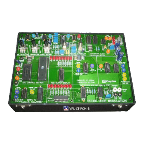
Pulse Code Modulation and Demodulation Trainer-Basic (VPL-CT-PCM-B)
TECHNICAL SPECIFICATIONS
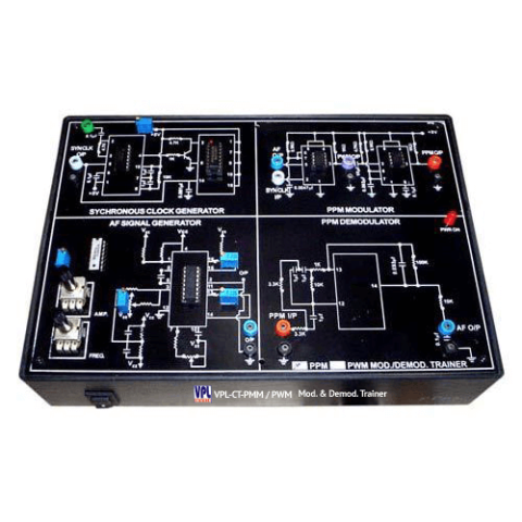
Pulse Position Modulation & Demodulation Trainer (VPL-CT-PPM)
Features:
- To study the Pulse Position Modulation & Demodulation
- Circuit diagram printed on pcb
- On-board Carrier Generator
- On-board Modulating Function (Signal) Generator with variable amplitude & frequency
- On-board Pulse Position Modulator
- On-board Pulse Position Demodulator
- On-board potentiometer for varying depth/percent of modulation
- Interconnection: 2/4mm banana sockets
- DC Supply: Built in IC regulated power supplies
- 220V ±10%, 50Hz mains operated
- Enclosed in an attractive ABS plastic cabinet with cover
- Standard Accessories: User's Manual with patch cords
Pulse Width Modulation & Demodulation Trainer (VPL-CT-PWM)
Features:
- To study the Pulse Width Modulation & Demodulation
- Circuit diagram printed on pcb
- On-board Carrier Generator
- On-board Modulating Function (Signal) Generator with variable amplitude & frequency
- On-board Pulse Width Modulator
- On-board Pulse Width Demodulator
- On-board potentiometer for varying depth/percent of modulation
- Interconnection: 2/4mm banana sockets
- DC Supply: Built in IC regulated power supplies
- 220V ±10%, 50Hz mains operated
- Enclosed in an attractive ABS plastic cabinet with cover
- Standard Accessories: User's Manual with patch cords
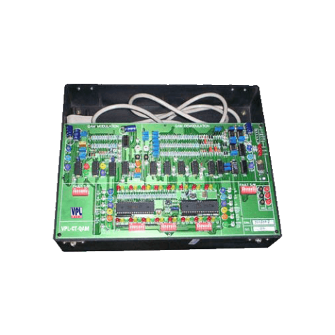
QAM Trainer (VPL-CT-QAM)
SALIENT FEATURES
- On – Board 24 data bit generator
- On – Board 4 phase generator (sine0, cosine0, -sine & -cosine i.e., 0°, 90°,180° 270°)
- On – Board Tribit Encoder - Decoder
- On – Board data switches for I, C & Q
- On – Board word clock generator
- On – Board Input / Output Buffer
- On – Board Test Points & Fault Switches
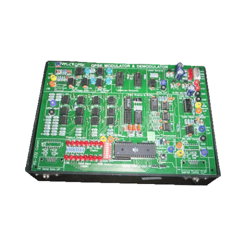
Quadrature Phase Shift Keying Modulation & Demodulation Trainer (VPL-CT-QPSK)
TECHNICAL SPECIFICATIONS
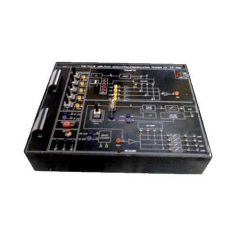
TDM Pulse Amplitude Demodulation Transmitter Trainer (VPL-CT-TDM)
SALIENT FEATURES
- Crystal controlled Clock.
- On – Board Sine Generator (Synchronized).
- On – Board Pulse Generator.
- 4 Analog input Channels samples and Time Division Multiplexed.
- Pulse Duty cycle selected.
- 4 Channel De multiplexer.
- Generation of clock at Receiver by PLL system.
- 4th order Butterworth L.P. Filters.
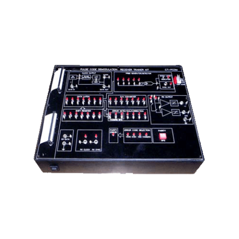
TDM Pulse Code Demodulation Receiver Trainer (VPL-CT-PCDM)
SALIENT FEATURES
- Input accepts two channel multiplexed data.
- On – Board De multiplexed PCM receiver.
- On – Board L.P. Filters.
- Fast and slow modes do real time operation & examination of control signal and data on LED.
- On – Bard Sync code Detector Error check code options:
- Odd or even parity single bit error detection.
- Hamming code – single but error detection.
- 4 switched faults for fault simulation.
- PC – PC communication via RS 232.
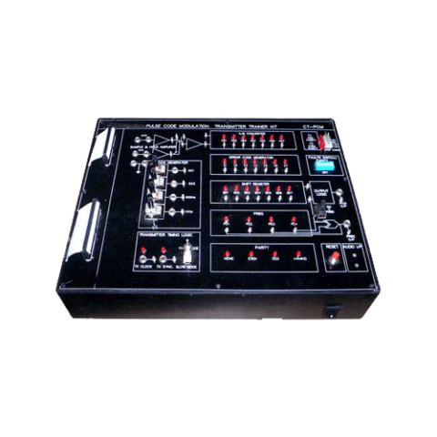
TDM Pulse Code Modulation Transmitter Trainer (VPL-CT-PCM)
SALIENT FEATURES
- Crystal controlled Clock & Sine Generator (Synchronized)
- 2 TDM Analog channels
- Error Check code option (Odd – Even parity, Hamming code)
- 4 switched faults can be used for error check & fault simulation.
- PC – PC communication via RS 232
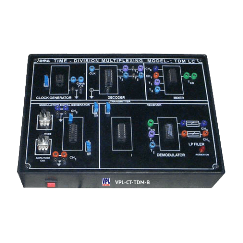
Time Division Multiplexing & Demultiplexing Trainer-Basic (VPL-CT-TDM-B)
TECHNICAL SPECIFICATIONS
- To study the Time Division Multiplexing & Demultiplexing
- Circuit diagram printed on pcb
- Data Generator 1 K b/s/Channel
- Low High, Logic Low sources
- Time Division Multiplexer
- Time Division Demultiplexer
- LED indication for channel outputs
- Interconnection : 2/4mm banana sockets
- DC Supply : Built in IC regulated power supplies
- 220V ±10%, 50Hz mains operated
- Enclosed in an attractive ABS plastic cabinet with cover
- Standard Accessories : User's Manual with patch cords
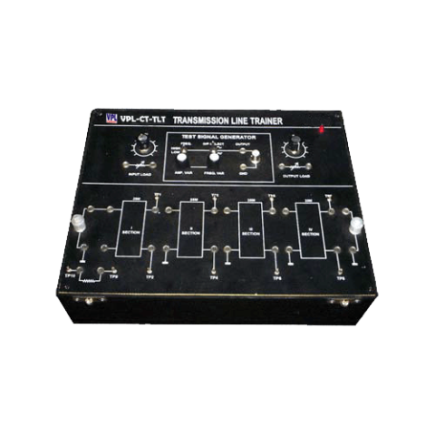
Transmission Line Trainer (VPL-CT-TLT)
SALIENT FEATURES