Satellite Communication Trainer (VPL-ST-06)

FEATURES
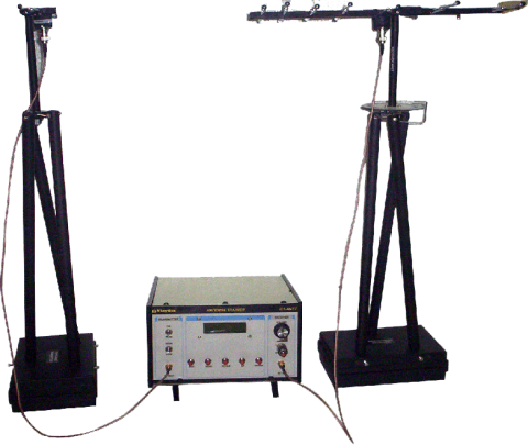
Satellite Communication Trainer has been designed to study completely about satellite communication system i.e. how a signal is transmitted and received using satellite standards. The complete unit consists of three sections; Satellite Uplink Transmitter, Satellite Emulator and Satellite Receiver. The satellite emulator receives signal from satellite uplink transmitter which can be analysed and emulated using various satellite instruments like spectrum analyzer. The received signal is then retransmitted to satellite downlink receiver where the signal is retrieved. The signals which are used for transmission are Audio, Video, and digital data. A provision to connect function generator is also provided.
- General Details
Using the above setup concepts like baseband analog signal parameters, phenomenon of linear polarization C/N ratio, S/N ratio, fading of a received signal, digital baseband signal parameter propagation delays can be studied. Data sent from one computer can be received on another computer using satellite link.
- Simultaneous communication of three different signals at each up-linking frequency.
- Communication of external broad band digital and analog data and base band signals.
- Choice of different transmitting and receiving frequencies.
- Transmission and reception with Helix, Dish Antenna is provided.
Note: Specifications can be changed and added without notice in our constant efforts for improvement.
- TECHNICAL SPECIFICATIONSatellite Uplink Transmitter
- Selectable 2.4 GHz band using keypad and LCD indication.
- 5/5.5 MHz audio and 8 MHz video FM modulation.
- Adjustable path loss knob to 30 dB.
- Transmission and reception with Helix, Dish Antenna is provided.
- Detachable dish antenna with separate terminals for different inputs.
- Transmit three signals simultaneously at each up-linking frequency.
- FM Modulation of audio and video.
- In built power supply.
Satellite Uplink Receiver
- Selectable 2.4 GHz band using keypad and LCD indication.
- Intermediate frequency 479.6 MHz (approx.).
- Various output terminals which are provided are Audio, Video, digital data up to 500 KHz, PC serial connector, Analog output, telecommand LED indication.
- Detachable Dish Antenna, Helix Antenna.
- Receives and demodulate three signals simultaneously.
- Built in speaker for audio and video output.
- Terminal provided for PC Interface.
- In built power supply.
Satellite Emulator
- Selectable 2.4 GHz band using keypad and LCD indication.
- Adjustable path loss knob up to 30 dB.
- Variable gain control knob.
- Emulation of variable signal fading, variable noise, and variable propagation delay.
- Detachable Dish Antenna, Helix Antenna.
- In built power supply.
Note: Specifications can be changed and added without notice in our constant efforts for improvement.
- Experiments That Can Be PerformedFollowing Experiments can be performed Using this setup
- To set up an active & passive satellite communication link and study their difference.
- To study the communication satellite link design: process of transmitting a signal to a satellite (UPLINKING), reception of same signal via satellite (DOWN LINKING) and functioning of
transponder of a satellite. - To measure the baseband analog signal parameters in a satellite link.
- To measure the signal parameters in an analog FM/FDMTV Satellite link.
- To study the functionality of a satellite MODEM.
- To measure the C/N ratio.
- To measure the S/N ratio.
- To study the effect of fading and measure the fading margin of a received signal.
- To measure the digital baseband signal parameters in a satcom link.
- To setup a RS-232 satellite communication link using com ports of PC.
- To measure the propagation delay of signal PC.
- To measure path loss using spectrum analyzer.
- To study noise on spectrum analyzer.
- Accessories
- The trainer provided with an interactive manual with complete details of theory and experimental procedure.
- BNC to BNC cables.
- Audio-Video Cable.
- RS 232 interface.
- Microphone.
- Mains Cord, Dish Antenna, Helix Antenna.
- Color TV (7″ TFT).
- Related Products
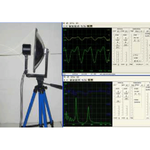
Advanced Communication Trainer (Antenna System) (VPL-VS-AT)
FEATURES
VPL-VS-AT PC Based Manual Antenna Trainer has been designed to provide useful tools for hands on experimentation and teaching of various commonly used antennas in VHF-UHF Microwave band in the laboratory for students of all levels. It can be used in standalone mode as well as be interfaced with a computer via RS-232 interface. In this Receiving antenna is rotated manually from 0 to 360 degrees and accordingly receiving antennas signal strength can be monitored on the Receiver.
Radar Trainer (VPL-RADAR)
Radar Trainer has been designed to study completely & demonstrate about the working and application of RADAR system. It is a self sufficient and complete setup of hardware and software to demonstrate Radar concepts and its applications. It is a great tool for Electronic & Telecommunication Lab/Department of any technical institute.
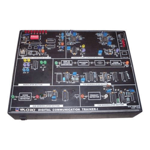
Digital Communication Trainer (VPL-CT-DCT)
This product VPL-CT-DCT is Digital Communication Trainer for demonstration and learning ASK, PSK, FSK modulation & demodulation experiments.
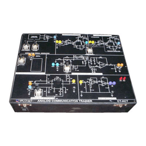
Analog Communication Trainer (VPL-CT-ACT)
This is our broad spectrum of Analog Communication Trainer. These products are passed through various parameters to ensure high efficiency. These are broadly praised for their trouble-free functionality that positions our product far ahead of our competitors.