Electronic & Communication Trainers

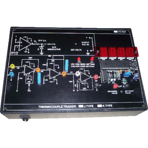
STRAIN GAUGE TRAINER MODEL (TT-SGT)
Trainer to visualise characteristics between strain applied & the voltage output, as well as the signal conditioned voltage of a cantilever strain gauge
Study Cards / Interfacing Modules
These modules can be connected to the I/O lines of any 8/16 bit Microprocessor Training Kit offered by us to perform experiments in the laboratory.
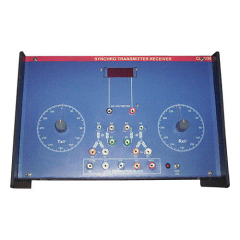
Synchro Transmitter Receiver Trainer (VPL-CL-STR)
DESCRIPTION
A Synchro Transmitter Receiver (STR) Trainer is an electromagnetic transducer commonly used to convert an angular position of a shaft into an electric signal. It is usually called a synchro transmitter. Its construction is similar to that of a three phase alternator. It consists of Sator, Rotor, Synchro Transmitter and Synchro Receiver.
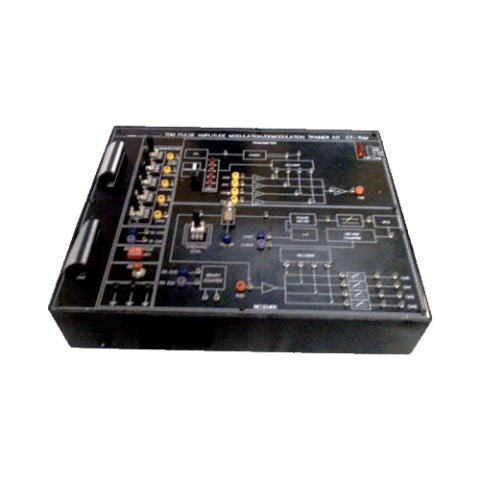
TDM Pulse Amplitude Demodulation Transmitter Trainer (VPL-CT-TDM)
SALIENT FEATURES
- Crystal controlled Clock.
- On – Board Sine Generator (Synchronized).
- On – Board Pulse Generator.
- 4 Analog input Channels samples and Time Division Multiplexed.
- Pulse Duty cycle selected.
- 4 Channel De multiplexer.
- Generation of clock at Receiver by PLL system.
- 4th order Butterworth L.P. Filters.
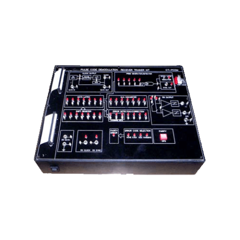
TDM Pulse Code Demodulation Receiver Trainer (VPL-CT-PCDM)
SALIENT FEATURES
- Input accepts two channel multiplexed data.
- On – Board De multiplexed PCM receiver.
- On – Board L.P. Filters.
- Fast and slow modes do real time operation & examination of control signal and data on LED.
- On – Bard Sync code Detector Error check code options:
- Odd or even parity single bit error detection.
- Hamming code – single but error detection.
- 4 switched faults for fault simulation.
- PC – PC communication via RS 232.
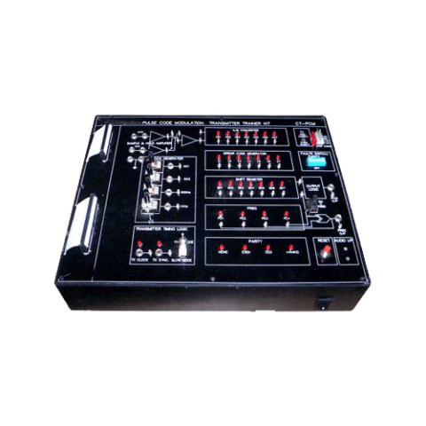
TDM Pulse Code Modulation Transmitter Trainer (VPL-CT-PCM)
SALIENT FEATURES
- Crystal controlled Clock & Sine Generator (Synchronized)
- 2 TDM Analog channels
- Error Check code option (Odd – Even parity, Hamming code)
- 4 switched faults can be used for error check & fault simulation.
- PC – PC communication via RS 232
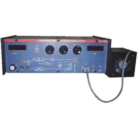
Temperature System Simulator (VPL-CL-TSS)
DESCRIPTION
This set up is designed to study performance of analog PID controller with model process as temperature control system. The set up has built in signal source as reference, digital voltmeter as temperature indicator, PID controller with separate controls and a model process with built in regulated DC supply to operate the system.

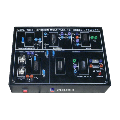
Time Division Multiplexing & Demultiplexing Trainer-Basic (VPL-CT-TDM-B)
TECHNICAL SPECIFICATIONS
- To study the Time Division Multiplexing & Demultiplexing
- Circuit diagram printed on pcb
- Data Generator 1 K b/s/Channel
- Low High, Logic Low sources
- Time Division Multiplexer
- Time Division Demultiplexer
- LED indication for channel outputs
- Interconnection : 2/4mm banana sockets
- DC Supply : Built in IC regulated power supplies
- 220V ±10%, 50Hz mains operated
- Enclosed in an attractive ABS plastic cabinet with cover
- Standard Accessories : User's Manual with patch cords
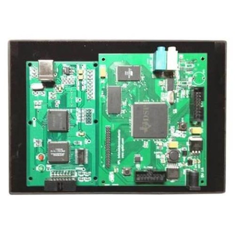
TMS320C6713 DSP Starter Kit (VPL-DSK-6713)
The TMS320C6713 DSP Starter Kit (VPL-DSK-6713) is a low-cost development platform designed to speed the development of high precision applications based on TI´s TMS320C6000 floating point DSP generation. The kit uses USB communications for true plug-and-play functionality. Both experienced and novice designers can get started immediately with innovative product designs with the DSK´s full featured Code Composer Studio IDE and eXpressDSP Software (optional) which includes DSP/BIOS and Reference Frameworks. All users will benefit from the eXpressDSP for Dummies textbook featured for the first time in this DSK.